Solar generators are great disaster preparedness tools that are worth getting if you can afford them. But they have a few problems.
- They’re expensive.
- They’re hard to modify. They lock you into a particular set of features that’s hard to expand on without buying a dozen different adapters, or taking the whole thing apart to cannibalize parts, and re-building the whole thing into a configuration you actually want with a lot of probably pretty sub-standard components. This is because they’re made by capitalists who will often cut corners to give you the cheapest (for them) version of the very expensive thing you think you’re paying for.
- They lack creativity.
If you can’t afford one of the myriad battery boxes you see advertised all over the place like Jackery and EcoFlow, building one yourself can save you some money. To be honest, even the components for DIY projects are getting so expensive that sometimes you save more money by buying something pre-manufactured. And I’m not even talking about “if you factor in the time you spend building it”. That’s just how fucked the supply chains are.
But DIYing a battery box offers a couple of advantages that the manufactured ones don’t.
- Less money all at once: You are able to spend money on one or two component at a time, rather than surrendering your whole paycheck to Jeff Bezos.
- Modular: You can configure these components in any way you want. You can add and remove parts, or you can easily cannibalize the whole thing later on if you need parts for a more pressing project.
- Repairable: If you know how to build it, you know how to fix it.
Ice fishermen have been building battery boxes similar to these for a long time. There are some significant differences in the end products because they’re built for different purposes. But if you want to build your own battery box, they might be a good source of information for you.
TOOLS USED
- drill
- step drill bit
- Oscillating tool / box knife
- wrenches/pliers
- Ratcheting wire crimpers
- Ratcheting PowerPole crimpers
- Automatic wire strippers
THE BATTERY
The most important component of the battery box is obviously the battery. Lithium Iron Phosphate (LiFePo4 or LFP) has pretty quickly supplanted Lead-Acid batteries and pretty much all other battery chemistries in the realm of amateur radio. The advantages of LiFePo4 over lead-acid are many:
- 3X higher energy density,
- more charge/discharge cycles,
- you can actually completely discharge a LiFePo4 battery without damaging the cells, unlike a lead-acid battery which can be damaged if discharged to below 20%,
- pretty constant voltage,
- no hydrogen gas or other fumes
- not made of literally brain-destroying lead or bone-melting acid.
And if you wonder why we didn’t choose Lithium Ion or Lithium Polymer batteries for this build, it’s because even though LiIon and LiPo are a little cheaper and have a higher energy density, LiFePo4 has a major advantage when it comes to safety: This type of battery does not catch fire nearly as easily as liIon or LiPo batteries.

A 100 Ah LiFePo4 battery is about the size of a car battery, but weighs only about 9kG (20Lbs). Unfortunately, there are about a thousand different brands of LiFePo4 batteries and only a few of them have “good” reputations, which are far more expensive than the other unknown brands. Long story short, quality control is kind of a crap-shoot on this stuff if you’re trying to save money, but the good news is that due to the LiFePo4 battery chemistry being very safe, your house (probably) won’t catch fire if it fails. But don’t worry, we’re going to take other precautions as well.
BTW, you can also build your own LiFePo4 battery from individual cells and a BMS, but that’s a whole other very deep topic, and something we haven’t tried yet.
In any case, we weren’t about to spend $900 on a fucking battery. We found a 100 Ah battery from a company called WattCycle for about $165. There weren’t a lot of reviews, but you can’t trust reviews anyway due to enshittification. There were no reports of explosions and it seemed like a decent price.
This battery can allegedly handle a maximum continuous discharge current of 100 Amps, which means it could discharge 100 amps for about 1 hour before the battery dies.
(Or 50 amps for 2 hours, 25 Amps for 4 hours, 12.5 Amps for 8 hours, 1 Amp for 100 hours, etc. If you don’t know what the Amp-hour rating on a battery means, now you know.)
We don’t really trust that statement, because that would mean that the wires going from the cells to the lugs would be at least 4 AWG copper wire, which is kind of expensive. We suspect that the people who made this battery are a little “smarter” with their money than they are with their mouths.
But it doesn’t matter, since we don’t expect to pull even half of that from this battery at any one time, and all connections will be fused anyway.
We’re using 12 AWG copper wire for most connections to the battery. 12 AWG wire can handle a maximum current of 20 Amps. And since none of these circuits should really pull any more than 15 Amps, that fits well within the 80% Rule. Our panel has 5 switches, and there’s another switch for the 20V circuit as well. Assuming each circuit would be On and pulling their maximum current of 15 Amps (a pretty unlikely scenario), that means that the maximum possible load we could put on the battery is 90 Amps which is ~allegedly~ well within the 100A spec for this battery. Furthermore, some of these circuits will actually have 10 or even 5 Amp fuses, so really we should be pretty safe.
Because of that potential 90 Amp total load, we actually need to use much larger wire to connect directly from the positive terminal of the battery to the 100 Amp cutoff switch, to the fuse block, and then to the negative side of the battery.
The battery’s BMS does have over-current protection, but it’s apparently programmed to quite a high current so we’re better off relying on our fused circuits. In theory, the BMS could be re-programmed, but it’s locked inside the plastic case and we don’t want to compromise any waterproofing that may provide.
The battery has high-temperature and low-temperature protection as well, because running the battery outside the -20°C to 60°C (-4°F to 140°F) range can cause damage to the cells.
BATTERY MONITORING
It’s important to have an idea of the battery’s state of charge, how much load is on it, and how much longer it can run. There are a lot of battery monitors out there. Mainly there are types that use a shunt, and there are types that use a hall sensor. Some even have Bluetooth built in so you can monitor the battery from your phone, but who needs another app.
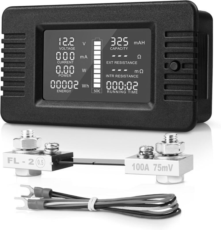
We chose a pretty cheap shunt-type battery monitor. There are instructions on the back that show you how to wire it up to a battery.
VERY IMPORTANT about these types of battery monitors: The battery monitor should be fully charged when you wire it up, otherwise the monitor will just assume that it’s fully charged when it’s not, and that could create problems and confusion down the road.
Another important point about these shunts, at least with a battery as large as the one we’re using, is that it took a VERY long time for it to “learn” what the capacity of the battery was. It needs to stay connected while it slowly counts how many miliAmp Hours the connected battery has.
THE SOLAR CHARGE CONTROLLER
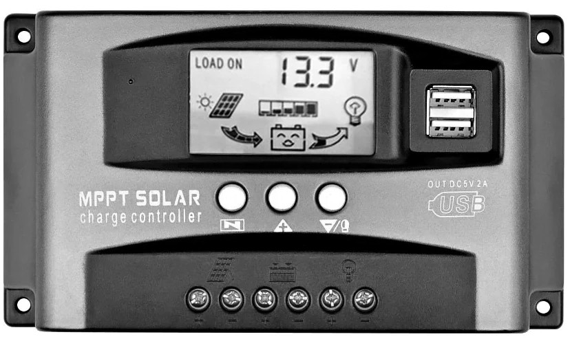
A solar charge controller is a device that sits between the solar panel and the battery and makes sure that the battery doesn’t get overcharged and that current flows only from the solar panel to the battery, and not the other way around.
There are two main types of solar charge controllers: PWM and MPPT.
PWM stands for “Pulse Width Modulation”. PWM charge controllers tend to be cheaper than MPPT, but they’re less efficient and they have a tendency to generate RF interference. Think of PWM as a switch that automatically turns off and on extremely fast in order to prevent too much power from getting to the battery and overcharging it.
MPPT stands for “Maximum Power Point Tracking”. These are much more efficient charge controllers that, generally speaking, generate less RF interference, but they tend to be more expensive.
There are exceptions to the RF interference. The PWM charge controllers sold by Bioenno have been shown to not create RFI, while the opposite is true of some of the cheaper MPPT controllers that are available. I myself have bought a 2-pack of PWM controllers, one of which created interference, the other of which did not.
Here’s what to do if you get a noisy solar charge controller. (Put ferrite beads on it.)
If you plan to generate power using a wind turbine, that’s a whole other can of worms. But here’s an article about that to get you started.
THE BOX
The box we’ve chosen is a Bauer modular rolling toolbox from Harbor Freight.
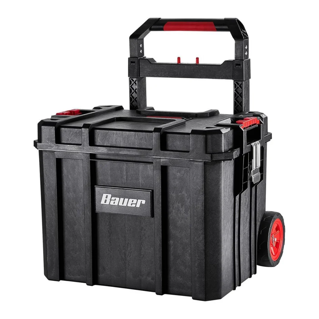
You can and should use whatever kind of container you want, but we think that due to their relative weather resistance, these modular stackable toolboxes – of which there are many brands, none of which are compatible with each other, of course – hold the potential to expand into a mobile modular system for different purposes such as ham radio, computer networking, or even a cooking station for a squat, encampment, or commune.
But if modularity and weather resistance is not something you need, you could easily build a similar system into a plastic tote, an old suitcase, or a wooden box. It’s up to you. Other types of containers would certainly fit better on a bike trailer than what we’ve chosen here.
“PANEL MOUNT” EVERYTHING

The trick to finding all the little ports you want on the outside of the box is to search “panel mount” or “chassis mount” in front of everything you need. Panel mount USB C, Panel mount Power Poles, Panel mount switches, Panel mount battery monitor, etc.
If you’re in a situation where you can’t have things delivered to you, look for an RV or boating supply store you can get to. They should have a lot of this stuff.
We bought most of these components on AliExpress. We know people have feelings about that sort of thing, but it’s the same place Amazon buys it from before they double the price.
WIRE AND FUSES
We went with 12 AWG silicone-jacketed copper wire for all the connections from the fuse box to all the connectors and devices. The maximum current rating for this wire is 20 Amps, which according to the 80% rule means we should really stay under 15 Amps for each circuit anyway.
We used 4 AWG copper wire for the main circuit between the battery, cutoff switch, and fuse block.
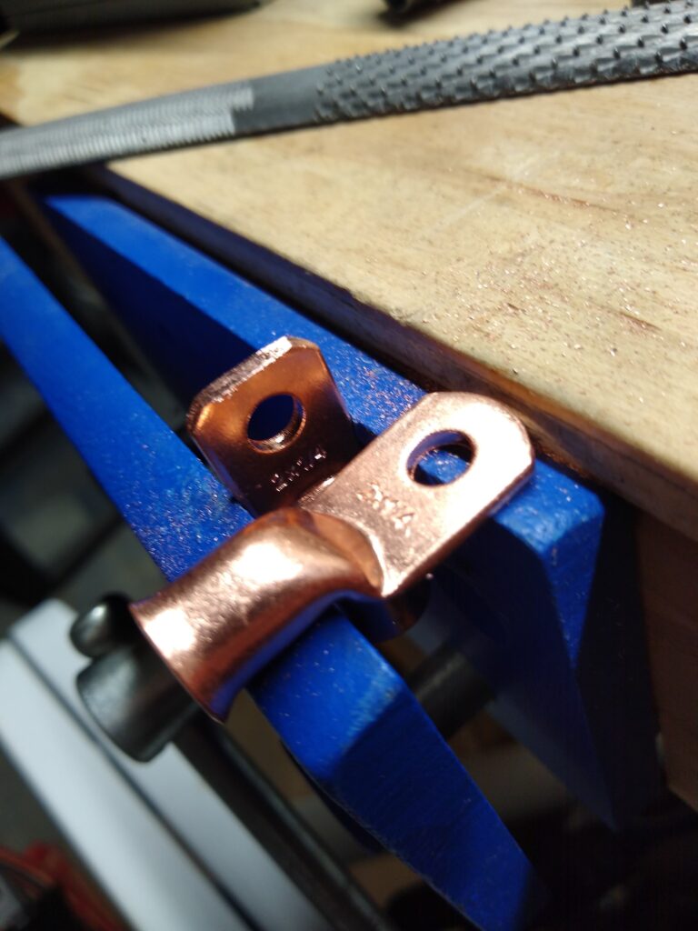
There are several tools for crimping large gauge cables like this. The best is probably a hammer crimp tool, but one of us already had a table vise so we used that instead.
If you are wiring two or more batteries together, you should definitely use at least 4 AWG wire or possibly even 1/0 welding cable in the shortest lengths possible between the batteries.
If you are wiring two or more batteries together, you should definitely use at least 4 AWG wire or possibly even 1/0 welding cable in the shortest lengths possible between the batteries.
The manual for our battery actually lists 12AWG wire as having an ampacity of 25 Amps. This may be true in most situations, but given that most sources say the ampactiy of 12AWG copper wire at 60 C is 20 Amps and we don’t really know how hot it might get inside this box, it’s just safer to go with the lower estimates.
Using wire that is too thin in any of these circuits creates a fire hazard!
So the “hot” side of each circuit will have a 15 Amp (or lower) fuse going directly to the positive side of the battery. It’s really a good idea to also fuse the negative side of each circuit as well, but 99% of problems that could cause a fuse to blow will occur on the positive side of the power source.
A mini-rant about Copper-Clad Aluminum (CCA) wire
TL;DR, Use pure copper wire if you can. Don’t use CCA wire if you don’t have to. If you do have to use it, use thicker wire than you think you need.
There was a short period of time in the 1970s in the so-called “US” when buildings were being built with copper-clad aluminum electrical wiring due to being cheaper than pure copper wire. The practice was generally abandoned after it became apparent that CCA wire tended to get much hotter than pure copper wire, creating a fire hazard. But it’s not like this was made illegal or anything. In fact, CCA wire is being used again in some newly-constructed homes, saving future slumlords literally TENS of dollars per McMansion.
CCA wire is also available online to regular people working on their DIY electronics projects, and it’s not always obvious what you’re getting. There is some math you can do to figure out what gauge of CCA wire should be used safely for a given current, but as far as we can tell it’s based on a combination of rules-of-thumb and straight up guessing the ratio of the copper-aluminum composition which doesn’t seem to be standardized. So it’s best to just look carefully and make sure you’re using pure copper wire.
THE INVERTER
We’re using a 500 watt “pure sine wave” inverter. This actually isn’t a very good inverter, but we really should only use the inverter as a last resort anyway.
The reason to avoid using an inverter as much as possible is because generally speaking, at least 10% of the energy is lost in the conversion (or inversion, as it were) from DC to AC. That might not sound like a lot, but when you consider that most of the small appliances we use on a daily basis actually convert the Alternating Current coming out of the wall into Direct Current, you’re basically simulating that same process by converting the DC of the battery to AC, and adding a whole new layer of inefficiency by turning that current back into DC so your device can use it. It’s an enormous waste of energy for most applications, but sometimes you have to do it.
This could be the difference between running a CPAP machine for one night or running it for 3 nights by using a DC-DC converter, so it’s important to think about this stuff.
The inverter came with its own 12 AWG wire and two 45 Amp fuses, so we ran this directly to the battery and ran a panel mount 120V AC receptacle to the front of the box.
https://www.youtube.com/watch?v=UAZGX379dmc Converting “ON-Grid” Electronics to “Off-Grid” – DC to DC Conversion – Everlanders
BUCK-BOOST CONVERTER
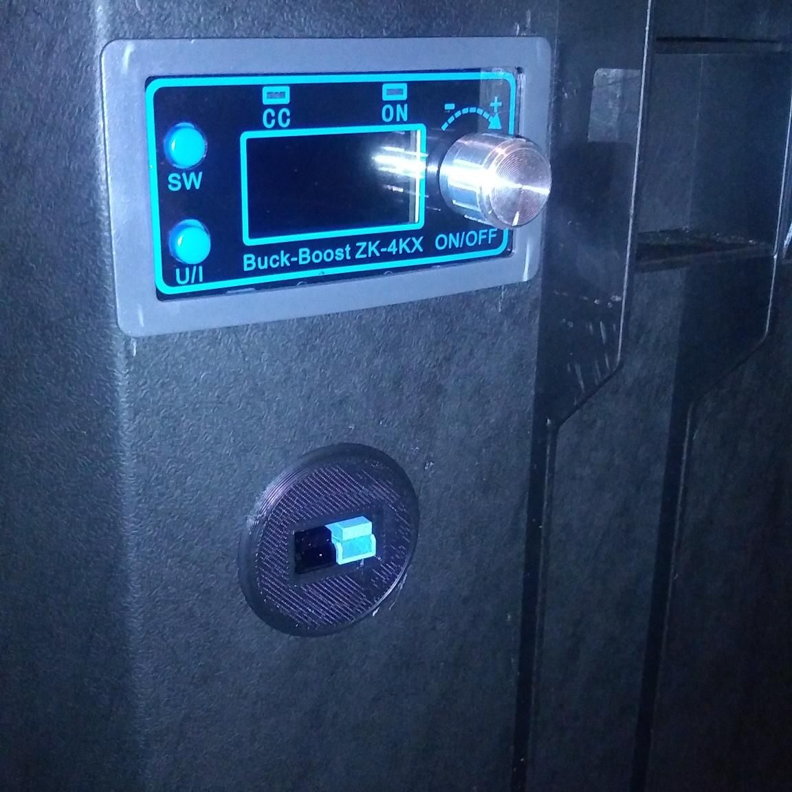
Due to the relative inefficiency of AC inverters, and an abundance of DC devices that require voltages other than 12V or 5V, we decided to do something we haven’t seen on other battery boxes. We’ve added a constant-current (CC) constant-voltage (CV) buck-boost converter. This is an adjustable DC-DC converter that can step the voltage up or down from 12V and supply it to a device at a specified current.
Mostly this is for laptops and power tool batteries which require about 20V DC.
There are a lot of guides out there on how to convert older hardware to be compatible with USB C and therefore be able to automatically negotiate voltage between source and load, but it’s a hell of a lot easier and cheaper just to snip off the cables that go to each of these devices and put Power Poles on them. In order to hopefully avoid confusion, we used blue Power Pole connectors on the positive side of the 20V leads, so that they are different from the red leads of the more common 12V connection.
https://www.youtube.com/watch?v=ZEa1fOCIAyE Boost Your Electronics Skills with Boost Converters. A Tutorial – The Post Apocalyptic Inventor
https://www.thingiverse.com/thing:3726066 PowerPole mount – ElectroAelex26
https://www.youtube.com/watch?v=ikTsE-UGN1s Xys3580 Dc Dc Buck Boost Converter Cc Cv 0 6 36V 5A Power Module Lab PSU Build – 1formatica
BUILD THE DAMN THING
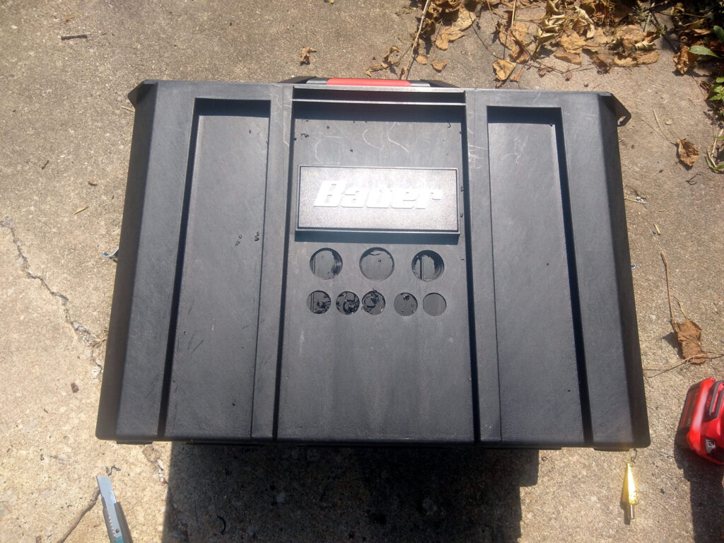
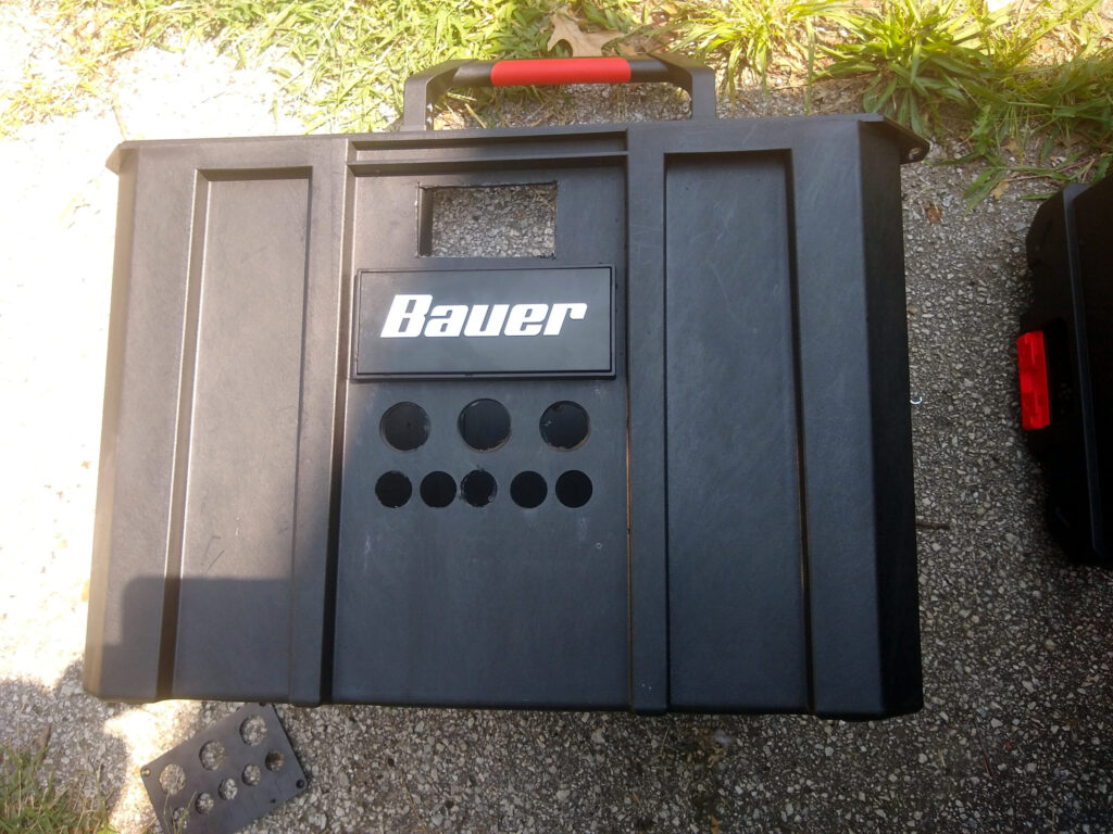
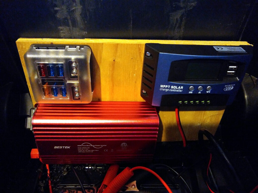
A group 24 battery tray was adhered to the bottom center of the box, and the battery was placed inside.
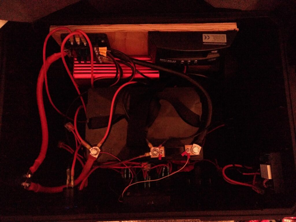
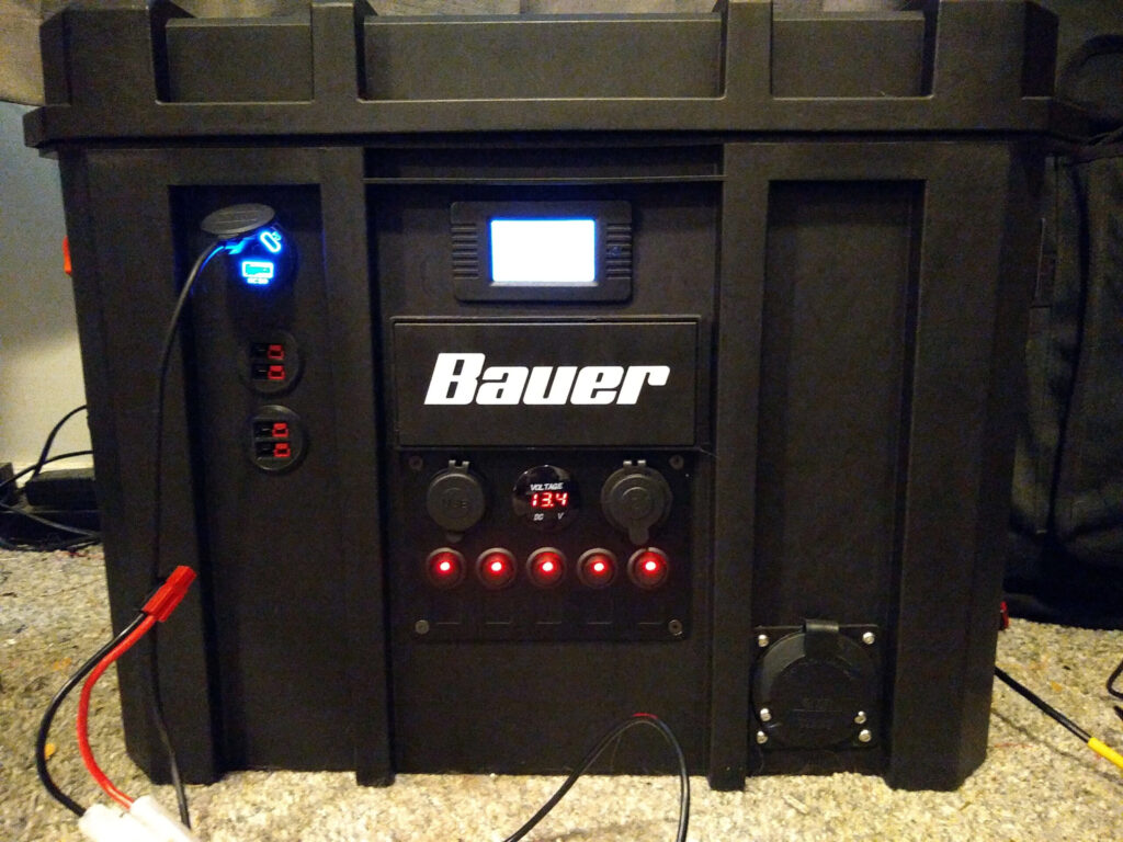
Aside from a lot of wire cutting, terminal crimping, and making sure the wires all go to the right places, that’s pretty much it! We would provide wiring diagrams, but they would probably just be more confusing than helpful, both for author and audience. Even though it looks like a mess in there, this stuff is not too hard to figure out once you’re sitting in front of it.
